I haven’t posted in a while, why? The quick answer is Old Radio.
When I was a kid in Eastern Washington, I spent many hours after sunset at the dial of our AM radio. From my basement bedroom, I ran a long wire antenna up to the eves of the house and clipped it to the whip antenna. I listed to the Canadian Broadcasting, Wolfman Jack, and some other stations which broadcast radio plays.
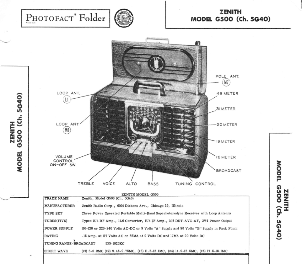
In the last couple of months I’ve become absorbed in restoring some old tube radios. I found a Zenith Transoceanic G500, which was advertised on Craigslist, as a barn find. The young man who sold it said he had (wisely) not turned it on as he was worried the old electronics might not be functional. I payed him $20 for the radio.
Since then, I’ve posted exactly two entries into the blog. Nights and “spare” time are now spent on the bench, learning how to fix these radios.
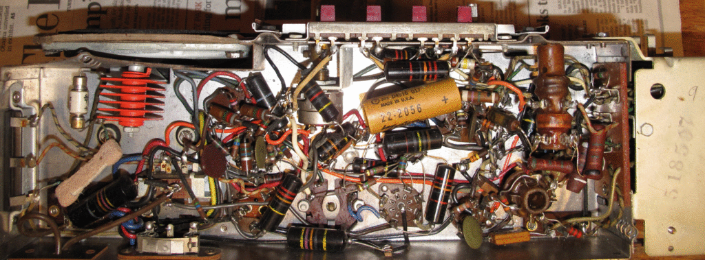
This is what is called “under the chassis” and what the electronics of the Transoceanic (ZTO) looks like. That and learning the schematics of this jumble has been challenging. Below is the functional diagram of the radio. This is one of three radios I plan on restoring.
The mechanics of restoring old radios is straight forward, a little cabinetry, soldering, and lots of cleaning. Things get tricky when you are trying to find a replacement for an old part you have just seen for the first time.
In the above photo “under the chassis” is a bright orange component on the left, this is a selenium rectifier. That is fine if you have a schematic for the radio and know how to read it. You might even know what a rectifier does in electronics. For me, I had no schematic for this model and didn’t know how to read them anyway.
Actually, I didn’t know which model it was to begin with. So, my education began by finding and reading the Antique Radio Forum (ARF). The people who populate this forum are heroes, they help people like me for “the cause” and try to keep us from killing ourselves.
I located other resources, one of which provides schematics for “free”. With the help of some ZTO enthusiasts on ARF, I was able to ID the model as a G500. From there, schematics were available from the Radio Museum (radiomuseum.org) and I was off and running, well stumbling is more like it.
Our local library had some great books on fixing old radios and how to read schematics, which I borrowed and read. I spent hours pouring over the schematic with a bamboo skewer in one hand the schematic in the other. I bought a cheap set of over your glasses magnifiers. I already had a good soldering iron and a good but small digital multi-meter (DMM).
The first thing you want to do when you get an old radio is plug it in and see if it works. The advice from the old timers is “don’t do that”. The reason is if the radio has a blown transformer, you might send AC current through the set frying all the components before you smell the smoke. The Zenith didn’t have a transformer so I merrily plugged it in and turned it on.
I was greeted with a horrendous HUMMMMMM and thought I had really screwed things up. I shut it off quickly and unplugged it. There was no smoke nor other noxious fumes so I didn’t burn anything out. What I had found out is that the old style paper capacitors were long past their prime and would have to be replaced. RECAPPING is what that is called.
Then I was told that my bright orange selenium rectifier would have to go too, it could go up in a greasy, smelly fireball at any time. And, while I was in there, I really should replace the candohm resistor and the zipohm resistor as well, both adjuncts to the Sel. Rectifier.
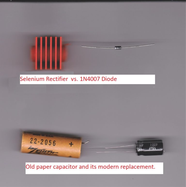
What that means in English is that this is a portable radio and runs on DC/battery power or can run on AC from the household current. The selenium rectifier and two above mentioned resistors turn AC power into the 105 V DC power needed by this radio. Very nice, but how do you replace 1940’s technology with 2018 components? You search the ARF forum and find that a 1N4007 diode will do that for you. You then add in some resistors to replace the old ones and try to hit the target voltage. This only took me five or six nights of tweeking and twiddling to get close to right, but it finally worked and that, coupled with replacing the old capacitors and mission accomplished, right? Just like GWB, nope, sorry it ain’t quite it.
This diode is the size of a modern transistor, it seems impossible that one could be the replacement of the other.
To be continued …


